Floating ball valves are more than just floating ball valves: Part 2
When floating seats are used in a floating ball valve, they can be one of two basic designs. They can either be self-relief seats, as illustrated in fig. 5, or double piston seats, as illustrated in fig. 6.
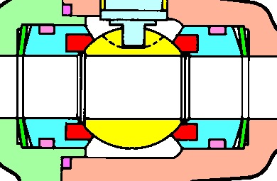
Figure 5

Figure 6
Regardless of which solution is used, the main seal of the valve will be its downstream seat, just as in fixed seat valves. The difference between the valves illustrated in figs. 5 and 6 consists of the way in which the upstream seat works. The seats in both solutions are spring-loaded and seal as upstream seats when the valve cavity is depressurized. Thus, both valves can achieve double sealing in the direction of the pressure (double barrier).
The fact that the seats in fig. 5 are self-relief means that the pressure inside the cavity forces the upstream seat away from the ball if the system is depressurized on the upstream side of the valve. There will always be some pressure left in the cavity; the amount of that pressure depends on the springs’ resistance.
The seats illustrated in fig. 6 are double-piston seats. This means that they are compressed against the ball when the system pressure comes from both outside and from the valve cavity, as illustrated in fig. 7. It is the same area that is being activated in both cases. On the left side, the external pressure pushes the seat against the ball and on the right side the pressure from the cavity pulls the seat against the ball. The big advantage of having floating ball valves with such a design is that the pressure inside the valve cavity can be increased and double sealing can be achieved by means of over-pressurization. This can be successfully used in low pressure systems.
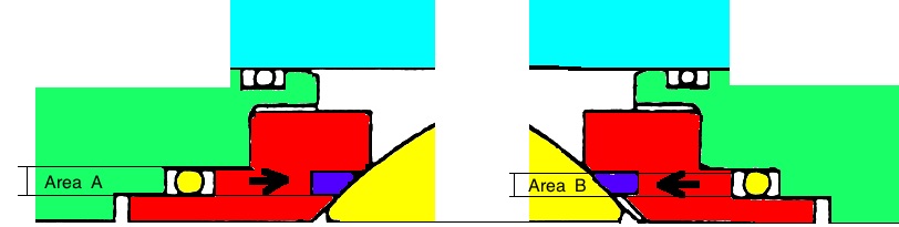
Figure 7
Since the force of sealing in low-pressure systems is small, making these valves completely leak-tight can be challenging. However, if we have a valve of the type illustrated in fig. 8, we can increase the pressure inside the cavity to as high as 20 bars, as shown in the example. We can use a neutral medium such as N2, water or lubricating oil, depending on which one is compatible with the system environment. Of course, the valve’s pressure limit must not be exceeded.
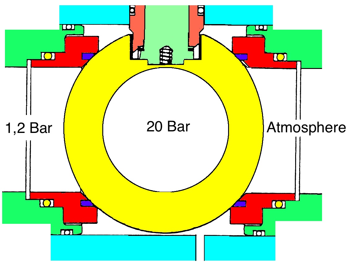
Figure 8
When creating double sealing, either by means of depressurization or over-pressurization, a prerequisite is for the valve body to be equipped with an auxiliary valve. There is hardly anything that can be done without such a valve. As mentioned in the first part of this article, it is unusual for auxiliary valves to be fitted in, nor are there normally any holes made in, the body of the valve so as to make it possible to control the pressure inside the cavity.
To be continued
Do you want to download this article as a PDF?
Click here to download