The how (and why) of maintenance part 11
The use of the auxiliary valve in ball/gate valves
As discussed in previous articles there is some important equipment witch is needed to be able to perform maintenance on valves. Without the lubrication fittings it is not possible to inject valve cleaner, lubricants or sealing component. When injecting into pressurized valves, leak lock must be used between the pump connection and the lubrication fitting, this as a safety device in the case of a leak through the fitting after the injection of cleaner, lubricants or sealing component.
An important part of the maintenance is being able to measure and control the leak rate passing the seats into the cavity of the valve. To do so a service valve connected to the cavity of the main valve is needed. In addition to the service valve there is a need of a gauge telling the cavity pressure allowing the calculation of the leak rate by reading the increasing pressure in the cavity of the main valve.
In earlier years it was “normal” to connect a ½” instrument valves to the cavity, but one must be aware of the fact that any valve connected to the cavity of a API 6D valve should be in accordance with API 6D, witch the instrument valves are not, and for that reason should not be use as a cavity auxiliary valve.
Fig. 59
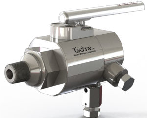
Figure 59
Resent years it has become more common to use modular valves (so called DB&B valves) as auxiliary valves on the cavity drain/ vent connection. The modular valves consist of one body with two valves and a bleed valve in between, and can of course be used connected to the cavity. But there are a couple of factors witch should be taken into consideration when it comes to modular valves:
- First of all the modular valves are large valves and in some cases heavy valves, witch may need extra support.
- If connected with tapered treads they are, because of the length and weight, easily breakable.
- In many cases it is impossible to install the modular valve on to the drain point due to the lack of space (the modular valve is quit long).
- When using an auxiliary valve in testing and maintaining a ball valve, the outer valve of the modular valve will be used as a throttle valve when depressurizing the cavity of the main ball valve. When using the last valve on the modular valve as a throttle valve, the seal surface will suffer weir and subsequently the valve will start leaking, and are no longer reliable when testing the main ball valve.
Together with the Italian machine factory Tèchne we have created a special auxiliary valve the AXY valve Fig. 59. The special features with the AXY valve are that the inlet of the valve can be threaded, raised face or RTJ in any dimension from ½” up to 2” but the valve itself will always be a ½” floating ball valve with metal to metal seal. This because the drain or bleed hole in the main valve will normally never be larger the hole in a ½” ball valve.
Fig. 60 Fig. 61
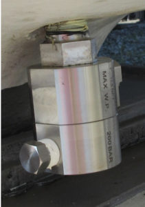
Figure 60
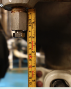
Figure 61
Fig. 62
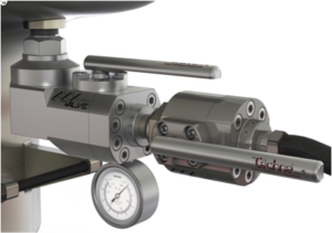
Figure 62
The outlet of the AXY valve will always be ½” NPT for connecting the service valve. The reason for this being, a service valve will be installed in the outlet of the AXY valve and used for depressurising the cavity and when testing the integrity of the main ball valve (see fig. 62). Between the outlet and the ball on the AXY valve there will be a ¼” test hole for installing a gauge, this gauge will be used to determent the leak rate passing the seats and into the cavity of the main valve. The outlet ½” NPT may be at the end of the valve fig. 62, or on the side of the valve fig. 59, it al depends on the available space. Fig. 60 shows an AXY valve installed where there was very limited space for a traditional valve and when it is be impossible to connect a hose to the end of the service valve, to vent the gas to a safe place.
Fig. 63
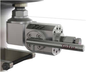
Figure 63
The ¼” test hole can be machined after the ball, as explained, or it could be machined between the main valve and the ball of the AXY valve, the gauge would then be permanently installed. In that case the AXY valve will become a tell-tail valve to be used for example on the stem of a major valve. The AXY valve will normally be in the closed position and as long as the stem seal is ok the gauge will indicate 0 pressure. But if there should occur a stem leak, the gauge will tell and indicating the increasing pressure between the AXY ball and the main valve, one can connect to the outlet of the AXY valve, open the AXY valve and inject sealing component to seal of the stem leak.
The AXY valve may be special made to fit in where there normally is no space for a valve like illustrated in fig. 61. In that case there was only 132 mm space between the clamp connector and the body threads (drain connection). Sideways there was no place to rotate a valve when installing into the threads of the drain-point.
To solve this problem, and at the same time only have one NPT connection, Tèchne constructed a valve in a 90-degree angle as illustrated in fig. 62 and 63. The valves are in two parts and the first part is screwed up into the main valve, then the ball valve part are bolted onto the part installed in the main valve. The AXY valve may have the handle on the side as illustrated in fig. 63 or it may have the handle on the top as illustrated in fig. 62. In fig. 62 the gauge is installed in the ¼” test port and the service valve is installed in the ½” outlet of the AXY valve.
The idea behind the AXY valve: When the AXY valve is installed and not in use the valve will be in closed position with a ½” NPT bleed plug in the outlet, and a ¼” blind plug in the test port and the valve will be secure in its closed position. The valve is a small valve witch does not require any support, and when needed for maintenance or setting a barrier, you install the service valve by open the ½” bleed plug and test the integrity of the AXY valve. Then disconnect the blind plug and install the gauge, disconnect the bleed plug and install the service valve, and the valve is ready to be used for testing of the main valve. Close of the outer service valve and quickly open the inner AXY valve, witch will stay in its open position until you are finished with the testing or maintenance. It is only the outer service valve witch will be used as throttle valve to reduce the cavity pressure. This service valve will after the job is done be disconnected from the AXY valve and the plugs will be reinstalled. The day the service valve starts to leak it will be fixed or replaced.
To be continued.
Do you want to download this article as a PDF?
Click here to download