The Story of the E-ball valve
During a valve course in 1989, an engineer challenged me to design a ball valve that would cope better to being opened under differential pressure, and seal more reliably than the conventional trunnion ball valve. The challenge for soft-sealing trunnion ball valves is both the problem of opening under differential pressure and that of impurities in the flow medium. Operation under differential pressure may cause the seat sealing to rapidly become damaged, and impurities in the medium may inhibit the necessary movement of the seat in the seat pocket. Both these problems can cause internal leakage.
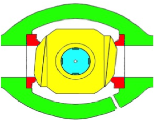
Fig. 1
I put my thinking cap on for a few weeks, and came up with a design where the sealing surfaces of both ball and seats is at an angle of approximately 85 degrees to the pipe, as illustrated in figure 1 – an eccentric ball valve. This design enables the seats to lock in such a way that they do not need to float in the seat pockets. A further advantage of this design is the large flow area all around the ball’s sealing channel as soon as the ball is released from the seats. This reduces the wear on the sealing surfaces – a considerable problem with traditional ball valves when opened under differential pressure. Since the sealing surfaces in my design are at an 85 degree angle to the pipe, there is mechanical sealing on both seats.
Based on this idea, the first construction drawings of the valve were made, and a patent application submitted. Anyone who has experience of patent applications will know that this is a difficult, demanding and extremely expensive process. The only option was to hold on tight and stick it out.
The first patent was issued in Norway in 1990, and then began the process of creating interest for it, so that production could begin. Since the valve’s construction was extremely complicated to manufacture, the valve would be very expensive – probably the most expensive ball valve on the market. This made it difficult to find a partner.
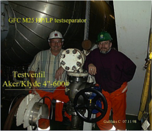
Fig. 2
Five years passed before Aker Maritime at Stord realised the valve’s potential. In 1995, an agreement was entered between Aker Maritime and myself, regarding the development and commercialisation of the valve; it was named the Aker/Klyde valve (my name at the time being Ingolf Klyde.)
The first step was to produce a valve that would be installed in an installation on the Norwegian Continental Shelf. Gullfaks C agreed to test the valve in their sand trap below the the HP/LP test separator, where they were experiencing significant valve problems. The photo in figure 2 shows Roy Hansen and myself beside the first Aker/Klyde valve which was installed on the Norwegian Shelf on November 7, 1998.
In this application, the valve was opened with full differential pressure, between 50 and 60 barg, and closed during full flow. In order to test the valve as thoroughly as possible, the valve was opened and closed 4-5 times each time it was operated. After about 250 operations, a minor leak developed at the intake seat and into the valve body, whereas the valve retained a tight seal on the output side. The adjustable stopper was adjusted by a quarter turn, and the valve intake seat again formed a tight seal.
Although the valve was functioning well, in May 1999 it was removed for inspection. This revealed a small degree of wear on the intake seats which had been the cause of the minor leak into the valve body. Following this, the valve was reinstalled and continued to function for another two years before being replaced by an equivalent valve. The test on Gullfaks C simulated 4-5 years of life in an application where the expected lifespan was just 6-12 months.
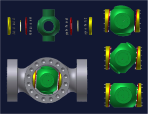
Fig. 3
The test was so successful that Statoil put in an order for a large number of valves to be installed in their produced water systems. The first delivery took place in March 2000. The valves were equipped with Cefilac sealing rings installed inside a two-part split seat as illustrated in figure 3.
Between April 2000 and November 2002, 73 valves were suppled, from 3″ – 6″ in classes 600 – 1500. Aker/Klyde valves were installed at the following installations: Åsgard A, Gullfaks A, B and C, Oseberg, Sleipner, Snorre, Statfjord C and Kårstø gas installation.
The valve underwent a range of tests, including an operational test where, after 500 operations, a leak rate of 20 drops per minute was discovered at 100 barg differential pressure. After 1000 operations, the leak was 35 ml per minute at 100 barg differential pressure.
In 2001, a sand slurry test was conducted to verify that the construction could cope with expected use. A 4″ class 600 valve was manufactured and installed into the 4″ test loop illustrated in figure 4. Figure 5 shows the valves installed in the test loop.
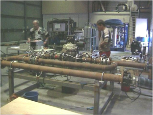
Fig. 4
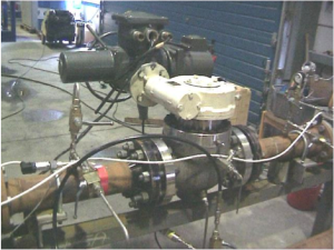
Fig. 5
The test loop was connected to a 6000-litre water tank, filled with 3000 litres of water and 30 kilos of fine sand. The pump that was used had a pump height of 65 metres (approximately 6.5 barg) and at full capacity had a flow rate of 5.5 metres per second.
The valve would be opened with a differential pressure of 100 barg, applied at the intake side of the valve after every tenth operation. Normal operation was opening with the differential pressure supplied by the pump, and closing in a flow rate of sand slurry of 5.5 metres per second. The valve’s operational time was set at 15 seconds from fully open to fully closed, and the same in the opposite direction.
The test results were no surprise. After 1000 operations, the water test at 100 barg differential pressure revealed a leak rate on the intake seat of 115 ml per minute, and the output seat had a leak rate of 35 ml per minute.
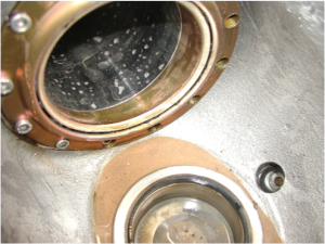
Fig. 6
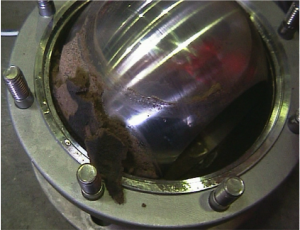
Fig. 7
When the Aker/Klyde valve was removed and inspected, the valve cavity was discovered to contain a minimal quantity of sand, as shown in figure 6. Since the flow into the valve body was on the outside of the ball, impurities in the valve body had been washed out in the current.
In contrast to the Aker/Klyde valve, the cavity in the conventional ball valves were full of sand (cf. figure 7). In each of the 4″ service valves there was approximately 200 g of sand, making operation very difficult. In addition, the pump’s impeller and seals had also been damaged during the sand slurry test.
Following the sand slurry test, further valves were ordered. However, now certain problems began to develop. After machining and assembly, problems were experienced with tests on large high-pressure valves. There were various reasons why the valves failed to function acceptably. One reason was a problem with the design of the seat and the machining of the valve parts. Because of these problems, in 2001 Aker Maritime entered a collaboration with Bel Valves to further develop and manufacture the valve. The valve was renamed the AkerBel valve.
One of the problems was the Cefilac seal. This proved to not be robust enough for the massive forces the valve was subjected to. The seat construction was changed to a two-part seat where the inner seat section functioned as a stopper and seal on the downstream side, and the outer section of the seat functioned as a spring and seal on the upstream side. Figure 8 shows how the orange seat functions as a stopper, and the yellow seat as a spring. This seat design helped to solve some of the valve’s problems. An additional challenge was the high degree of precision required in the machining of this valve; maximum tolerance could only be a few hundredths of a millimetre. To avoid scratching, the contact surfaces were coated with a hard material; the seats needed to be flexible, but without causing the hard coating to crack. Challenges piled up, but were solved one by one.
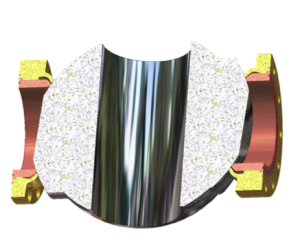
Fig. 8
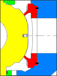
Fig. 9
In 2004, Aker Maritime withdrew, and Bel Valves took over control of production. The valve changed name once more. From 2004 onwards, the valve has been known as the E Ball valve. “E” stands for eccentric, thus the term eccentric ball valve.
From 2004 until present time, there have been a number of tests on the valve construction. Variable seat constructions have been investigated, seat materials adjusted, different coating techniques used, as well as tests using different qualities of the hard material used to coat the valve’s sealing surfaces. One of the developments to the seat design is that the seat is no longer a single two-part seat, but the seats now consist of the red spring section illustrated in figure 9.
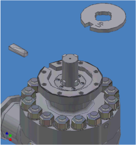
Fig. 10
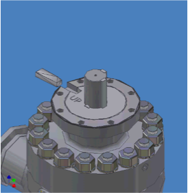
Fig. 11
If the valve is used as a double-sealing valve, it can be manufactured with a locking system installed between the gear/actuator and the valve body. The lock plate illustrated in figure 10 is permanently mounted in the bonnet as shown in figures 11 and 12.
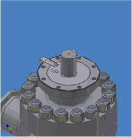
Fig. 12
When the valve is in closed position, the wedge is inserted into the groove in the bonnet. The wedge thus locks the spindle rotation preventing further operation. When the valve needs to be operated again, the wedge has to first be withdrawn from the groove. Since system pressure at the inlet side of the valve forces the ball towards open position, the wedge prevents system pressure from reducing the quality of the seal if the cavity is depressurized with the gear or actuator dismantled. Without the lock the valve will still be a double-sealing valve, but the lock will help to secure the seal in special situations.
Between 2003 and 2013, Bel Valves Ltd have suppled 202 E Ball valves to the Norwegian Shelf. The valves have primarily been installed in the fields Gullfaks, Oseberg and Snorre. The valves are manufactured using either 22% duplex chrome , 25% duplex chrome, super austenitic acid-proof steel, 18% acid-proof steel or carbon steel. The valve is now fully NACE compliant and capable of sour service.
E Ball valves are generally used in the most demanding applications or where a single mechanical double-sealing ball valve is required as an isolating valve.
Since the seats are fixed inside the valve body, the valve is not dependent on floating seats that are affected by system pressure. Floating seats are easily put out of action by friction in the seat pocket or sediments deposited behind the seats. The idea behind the valve design was to develop a robust double-sealing valve that would require less maintenance. It was also designed to be better able to cope with being opened under differential pressure and closed in full flow.
Further information about the E Ball valve may be found on the Bel Valves website: http://www.belvalves.co.uk
or the E Ball valve webpage:
http://www.belvalves.co.uk/wp-content/uploads/BV-Dbl-ISO-Ball-Valve-DS-1511.pdf