Double block & bleed: understanding a barrier – part 5
When preparing for å job to be done most production personnel in the hydrocarbon industry are focused upon the double block & bleed. For a job to be safely done everything has to be in accordant with the company policy, witch normal are double block & bleed up to the point where the job are to be done. But it is not always that simple, one can end up in a situation like on I was involved in many years ago.
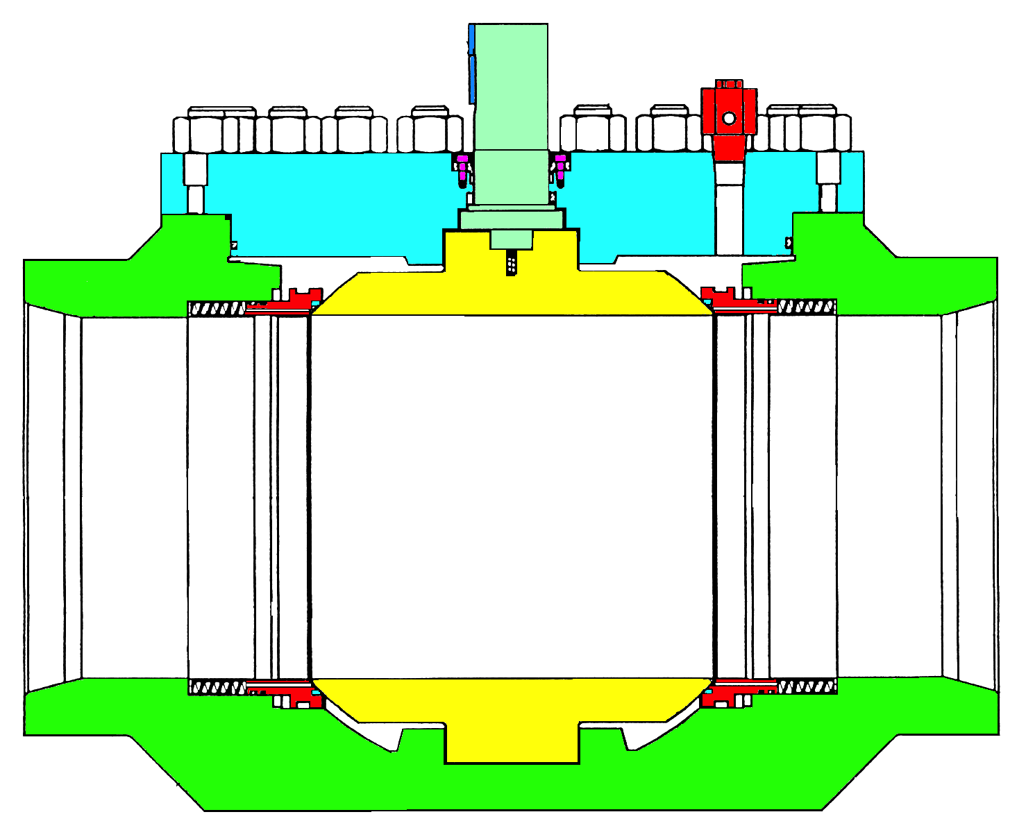
Figure 22
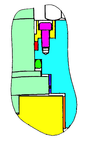
Figure 23
There was this 36” pipline valve illustrated in figure 22, an ESD export valve on a platform in the Norwegian sector of the North Sea (152 bar gas). The valve was a top entry trunnion mounted ball valve with seats of the self-relief type. It was an in welded valve and there was a major spindle leakage every time the valve was operated. The leakage stopped around 30 minutes after operation both towards open and closed position.
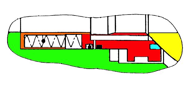
Figure 24
As illustrated in figure 23 there were no lubricant fitting into the stem seal area and there were one O-ring (green) under the bonnet and one graphite packing (red) above the bonnet under the yellow packing retainer. Preparing for this job there were several facts to consider:
There was no balance hole in the ball.
There was one vent plug on top of the bonnet, figure 22.
On drain valve was installed at the bottom of the valve, not on the drawing
The seats were of the type SR with soft seals, figure 24.
No lubricant fitting to the stem packings, figure 23.
400 km to the next valve on the down stream side.
There was no way of getting double block and bleed on the down stream side of the valve without blowing down a 36” and 400 km long pipeline, or setting a hydraulic plug after the valve. Both alternatives were a multi million project demanding many days of total shut down through that pipeline.
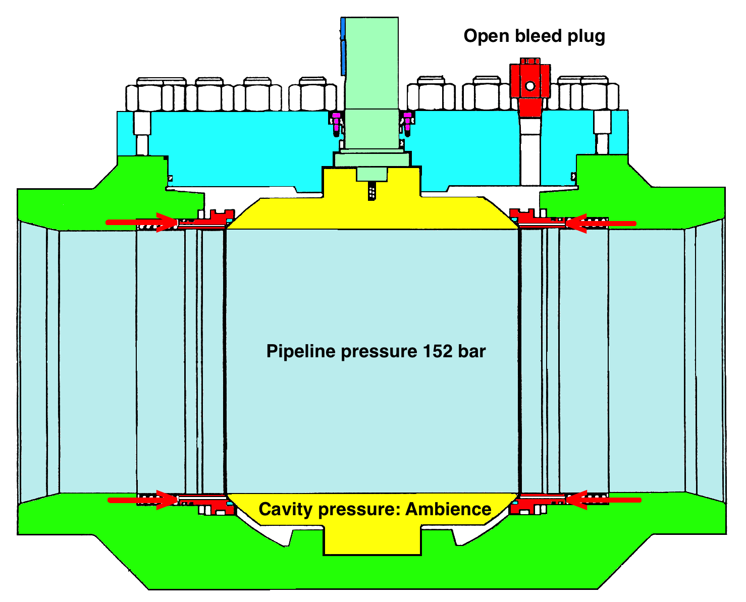
Figure 25
My suggestion in this situation was to replace the graphite packing under the retainer with a special made O-ring and a spacer to fill in the extra distance between the O-ring and the retainer plate. To keep the ball in balance I suggested doing the job with the valve in its open position. There were a lot of discussions concerning this, as they felt safer working with the valve in the closed position. But if looking at the valve in figure 25 you will see that there are no differences whether the valve is in open or closed position, it will be the same soft seal on the seat making the seal against the ball. The seal force that the system pressure compresses each seat again the ball was calculated to be equivalent to around 35 tons. With the valve in the open position the force from the pressure inside the ball bore was totally balanced. If the valve were in closed position any reduction in the pressure on the platform side would make the pipeline pressure force the ball to one side and possibly create problem re installing the retainer plate. In worse case any tilting of the ball could create a leak past the seat/ball seal. By keeping the valve in open position this problem was avoided. This could be done because the ball was without a balance hole.
The valve was operated to its open position, but the production on the installation was stopped as this made the HMS personnel feel safer. But it did not matter as the downstream side of the valve was filled with trillions m3 with gas; it´s all in the head. After 30 minutes the bleed plug was opened, left open for 15 minutes and the valve did have a small leakage that could be measured close to the bleed plug, but not in a10 cm distance. Both seats sealed perfect towards the ball but there was some small scratches on the soft seal of one or both of the seats. The drain plug was closed and the bottom drain valve opened.
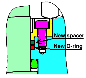
Figure 26
Now the actuator was disconnected and removed. There were no increscent of the leak rate out the drain valve. The retainer plate was removed and the graphite packing taken out of the groove. New O-ring and spacer were already produced, so the packing groove was cleaned, lubricated and the O-ring was installed with the spacer on top as illustrated in figure 26. After installed the retainer the cavity was slowly pressurized with N2 up to production pressure 152 bar. The O-ring was tested with snoopy and not a bobble registered.
It took me 20 minutes from I started removing the retainer plate until it was back in place with a new O-ring. After the O-ring was tested and accepted there came a comment from the platform manager: Was that all? Where I had to answer: Yes that was it.
That was a perfect safe operation, but not in accordance with the company policy of double block & bleed. As I have stated earlier: It´s all in the head, you need to have personnel that know how valves work and how to maintain them in a safe way. Sometimes the struggle for double block & bleed are making the operation more dangerous. The most important issue is to do it SAFE.
To be continued.
Do you want to download this article as a PDF?
Click here to download