Do end-users really care about fugitive emission, or do they only want cheaper valves? Part 1
Do end-users really care about fugitive emission, or do they only want cheaper valves? Part 1
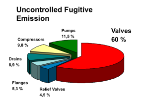
Fig. 1
May be this is a provocative questions, it´s ment to be. In the resent years there have been written miles by miles with articles and recommendations, there have been preformed tests and there have been developed new product, so fare so good. If we take a step back in time and look at the tests carried out in the 1990´s it was discovered as fig. 1 shows that 60% of all fugitive emission was related to valves. On a valve there are two types of seals, there are static or dynamic seals: The flanges and the bonnet are static, and the spindle are dynamic because it is moving. With regards to the valves leaking in fig. 1: Witch seal is most likely to be the main leak-source of the leaking valves? Right, the dynamic seal on the spindle.
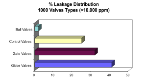
Fig. 2
If we take a look at fig. 2, that graph shows that out of 1000 valves leaking more then 1% (10 000 ppm) only 2% was ball valves, 24% control valves, 32% gate valves and 42% globe valves. How come?
Then we can take a look at how the valves are operated. Witch valve type does have most spindle movement, when the valve is operated? The globe valve – since the movement usually is rotating and rising. The next in line is the gate valve, where the spindle movement is normally rising and not rotating. The control valve are rising but usually does not move all the way up and down as the gate valve does. And the ball valve have the least spindle movement of all with only 900 back and forth. Witch valve seal are exposed to most wear and tear due to operations? You don’t have to be a scientist to come to the right conclusion.
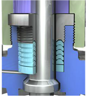
Fig. 3
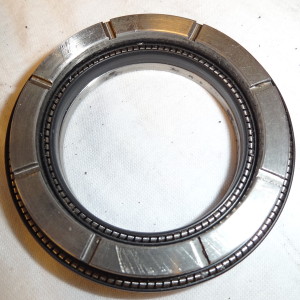
Fig. 4
Then we can ask the question: Is the situation different to day, then back in the 90´s? The answer is: Yes and No. Yes, the leak rates are reduced doe to better qualities of packings, (when they are used), but no, the globe valve spindle area are still the no. one leak source on valves, and the gate valves a good no. two, the ball valves still in the font.
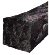
Fig. 5
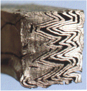
Fig. 6
Now we have to take a look at how the different spindle seals are functioning. There are two main categories spindle seals: 1) sealing by means of pressure from the media, and 2) seals due to compression of the packing material. The first category are Chevron rings or Lip-seals, (O-rings are not taken into consideration), the difference between Chevron rings and Lip-seal are that Chevron rings are usually a stack of rings on top of each other as showed in fig. 3, but Lip-seals are normally only one ring as fig. 4 shows, where there in this case are one ring as inside (spindle seal), and one on the outside (bonnet seal). Both seal systems need a preload on the seals to function. The Chevron rings get the preload from the compression ring above the chevrons when installed. The preload of the Lip-seals comes from the spring between the lips, inside the ring.
So much for the pressure activated seals, for now. Over to the compressed packings. There is a range of different material used, but we will deal with Graphite, since that is the most commonly used material in compressed packings for the hydrocarbon industry. There are two basic ways of producing graphite spindle packings. Fig. 5 shows braided packings that normally comes as lacing on a role, and Fig. 6 shows die formed packings that normally are produced in rings.
To be continued in next issue.
Do you want to download this article as a PDF?
Click here to download