The how (and why) of maintenance part 3
To be able to maintain a trunnion ball valve one must have access to the interior of the valve. For that reason the valve should be equipped with lubrication fittings and auxiliary valve/s. As discussed in part one and two in this series the number of injection points and internal seat canals needed, must be seen I relation with the dimension of the valve.
If you do have four injection points to the seats in a 24” class 900 valve you have the possibility to inject valve cleaner and do have a good chance having success with your maintenance. But having injection points and an auxiliary valve in the cavity does not guaranty any improvement if you preformed your maintenance without being in control of the situation.
There are two main ways of doing maintenance, 1) you can do what you think is right and hope for an improvement, but without you knowing what happened and why it happened. Or 2) you can analyse the valve and the situation, and do things under control knowing what is happening and why.
Some month ago I came offshore to an installation to try to save some valve witch already had been maintained but failed any improvement. Before starting any maintenance I was talking to the personnel that had been working with the valve to get information about what had been done with the valve. Normally before doing anything on a valve there are some important issues that must be clarified:
- You need the GA drawing of the valve with a blow up of the seat construction.
- You must know the media passing through the valve.
- You must know the operation conditions of the valve compared to the seal quality.
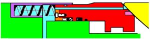
Figure 11
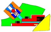
Figure 12
To start with the GA drawing of the seat in fig. 11, it shows the seat construction of a top entry self-relief valve. One can see the distance for seat retraction on the backside of the seat and the spring retainer also at the back of the seat.
Looking at fig 12, witch is the seat of a split body self-relief valve. Comparing the free volume (blue) on the back of the seats one can clearly see that the volume of fig. 11 are many times the volume in figure 12.
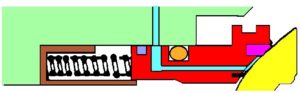
Figure 13
When injecting valve cleaner in the valve, the blue volume indicated in fig. 11 and 12 must be filled for the valve cleaner to come into the seal area of the ball and the seat.
There is a rule of thumb when it comes to inject valve cleaner and sealant component into a trunnion ball valve, and that is:
One should inject 1 once / inch bore of the valve per seat. That would be sufficient to the seat in figure 12, but NOT the seat in figure 11. Because of the large volume due to the seat retraction distance that seat needs the double of the volume to be filled with enough valve cleaner.
But this is not the case for all top entry ball valve. If looking at the illustration in fig. 13 witch is a top entry valve with seat retraction one can see that the injection canal enters radial to the seat and there are no need for the filling of the retraction distance on the back of the seat. The illustrations in fig. 11 – 13 are just some of the seat constructions on the marked. So, before start pumping any substance into the valve, you must find out how much to inject.
In the case I was telling about in the start of the article, they actually did not have a clue what seat construction was in the valve and had not injected the sufficient volume to clean the seal area. Doubling the amount of valve cleaner was all it took; the valve sealed and did not have to be replaced
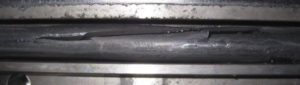
Figure 14
When it comes to the second point, the media, there is quite a difference in the valve problems that occurs in gas versus water or oil. If using O-rings as the main radial seal on the seats in a gas service, the photo in fig 14 illustrated how ED (explosion decompression) is an important factor to consider. In fact some oil companies have banned the use of O-rings in valves situated in gas service. And we will look at the impact lip seals versus O-rings can have on the valve performance in a later article.
The third point to be considered was the operation condition of the valve compared to the seal qualities.
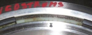
Figure 15
As illustrated in the photo showed in fig 15, the worse condition for any soft sealed ball valves are a throttling situation. The first (and last) operation part of the opening / closing of a ball valve can result in blowing the soft seal out of the groove. Some companies have a restriction on valve operation with DP, witch states that soft seated ball valves should not be opened with a DP higher then 20 bar. And metal-seated valves should not be opened with a DP exceeding 60 bar. But 10 bar can blow the soft seat out of the groove if the valve was left 20 % opened over a longer period of time. The metal-seal on the seat can be totally destroyed with 20 bar DP in an liquid media, if the valve opening was small enough.
To be continued.
Do you want to download this article as a PDF?
Click here to download