Maintenance on the Christmas trees part 1
As the year 2015 is closing up an we are getting close to Christmas it is in this world of valves natural to think of Christmas trees, not the ones in the living room made of wood or plastic, but the X-mas trees on the well head or on the sea-bed securing us the flow of oil or gas from the reservoirs down in the ground.
The X-mas is the first barrier and most important group of valves controlling the hydrocarbons after passing the seabed or the ground. To secure this group of valves a long and well functioning life they need to be treated and maintained in a proper way. This leads us to an important question; How are those valves to be maintained? This is not an easy question as it all depends on how the valves are equipped, how they are operated and how the media is passing through the valves.
I many times have heard the statement that all X-mas trees must be greased, witch actually are fare away from the truth. So what do decide how the X-mas trees should be maintained?
First of all, lets look at the media going through the valve and witch way the media flows.
There is quite a difference if the media are clean gas or water to be injected or polluted crude oil coming up from the ground. In the the case of a clean media I don’t think I would inject anything into the cavity, but maintained the valve by partly stroking (inching) the valve 15% in both open and closed position 3-4 times a year if possible, this to keep the seal area clean. A valve standing in the open position a year or more can easily get a build up of residues on the close seal area, you only needs tenth of millimetre to get a leaky valve, illustrated with the arrows in figure 1. Operating the valve regularly may prevent this build up and keep the seal area clean.
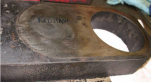
Figure 1
To be able to do maintenance on any valve regardless of type or dimension there is a need of lubrication fittings and/or auxiliary valves installed on the valve body. I won’t hide the fact that there are different opinions about those fittings/ valves. Some regards them, as leak point witch should be reduced as much as possible, others as a cost increasing items and others like me look at them as a tool for maintenance of the valves. It has to be said that those fittings/valves should only be installed on the valve when needed for maintenance. No one would dream of installing those fittings on a sub sea valve.
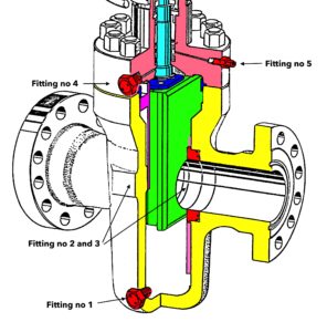
Figure 2
So on witch valves should those fittings/ auxiliary valves be installed? We are now addressing the gate valves. First let us have a look at figure 2 and the placement of the fittings. Fitting no 1: This is the drain point where the fitting could be replaced by an auxiliary valve to increase the bleed area. The drain point should be on the lowest point when the valve is installed This drain point is ideal to reduce the cavity pressure to test the seat integrity or to set the valve in a double block position. Fitting no 2 and 3: This is injection points to inject valve cleaner to clean the seat/gate seal area, or to inject sealing component to seal of the valve in case of small internal leaks. On valves larger then 8” there should be two fittings to each seat. Fitting no 4: This fitting has two functions, one is to test the back seat in case of a external stem leak, and the other is to inject body filler or dissolvent into the cavity. Fitting no 4 can also be used as a vent in case of liquid filling of the cavity. Fitting no 5: This is a lubrication or sealing component injection point to be used if the stem seal needs lubrication or in case of a external leak passing the stem seal.
In addition to reduce build up on the seal area of the gate there are several other reasons way well head valves need maintenance. There are still company using gate valve components and valves made by carbon steel, and as we know carbon steel corrodes. To prevent corrosion on internal parts the entire valve cavity should be filled with body filler (grease). Body filler will also act as a lubricant and reduce friction on all moving parts inside the valve.
To be able to fill the entire cavity it is important that the fitting no 1 is at the lowest point of the body and fitting no 4 is at the highest point of the body as the valve is installed in the X-mas tree. If the fitting no 1 is missing and the valve is only installed with the fitting no 4 it is impossible to fill the bottom of the cavity with body filler if the cavity is filled with water or any other unvented liquid that has to be drained to fill with body filler.
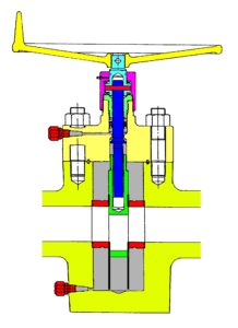
Figure 3
If the cavity is filled with body filler it is important that the seats are equipped with skirts, illustrated in figure 3. The skirts will hold the body filler inside the cavity and reduce the consumption if the body filler when the valve is operated, closed when flowing or opened with a differential pressure. Figure 4 illustrates what happens when operating a valve without shirts to hold the body filler inside the cavity. There are no use in filling the cavity with body filler and then suck it out of the cavity at the first operation.
There is one other difference comparing figure 3 and 4. In figure 3 there is two injection points and in figure 4 there is only one. In the valve illustrated in figure 4 it will be impossible to fill the lower part of the cavity with body filler.
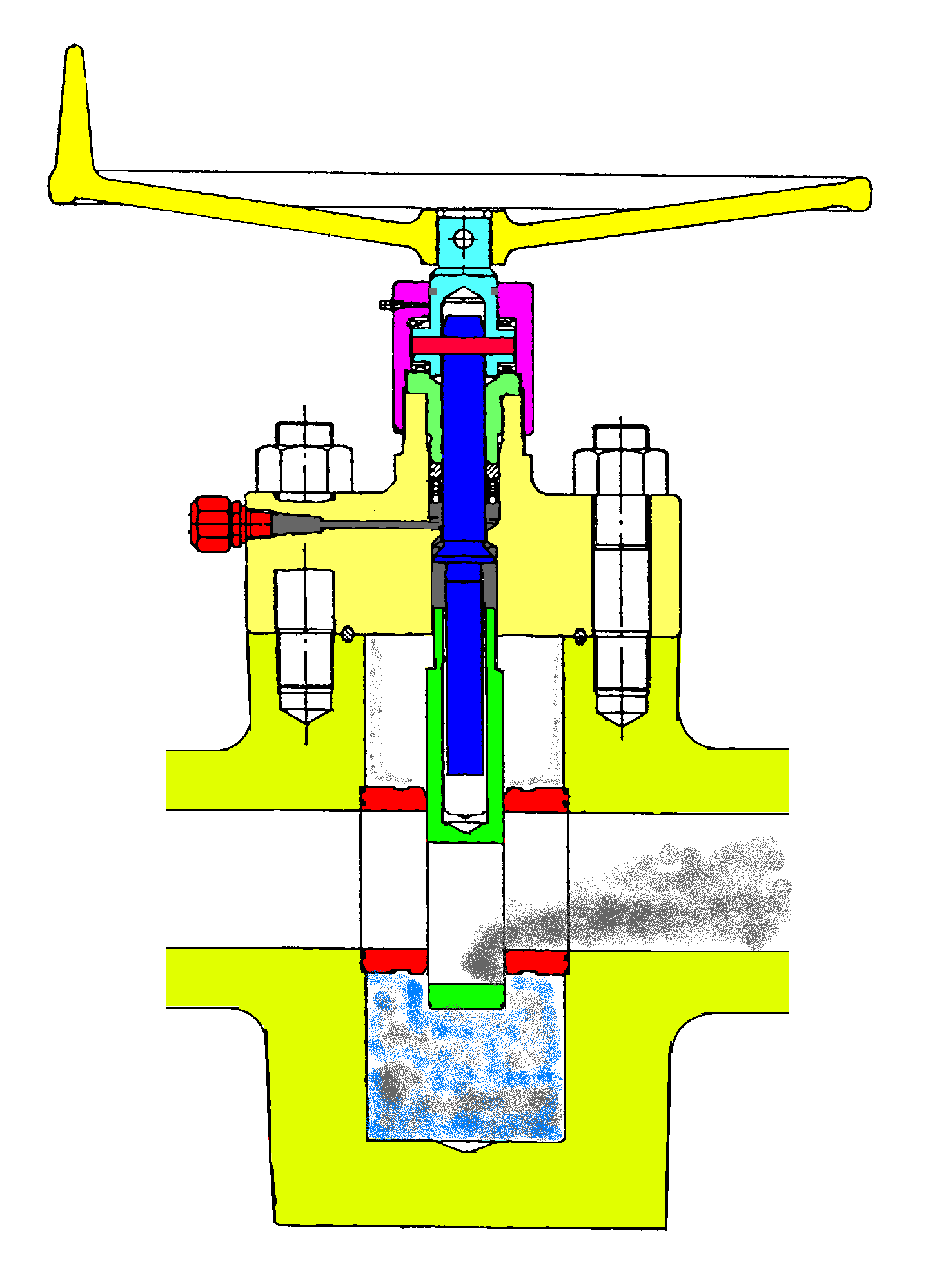
Figure 4
When maintaining a well head valve it is not un-normal to refill with body filler the same volume as in the cavity. This is fine if the valve is equipped with two fittings (figure 3). In that case you can drain out the old body filler. But in the case of having only one fitting and having skirts the whole volume of body filler goes into the production line.
There is some other important aspect to consider. That is how often are the valve operated, and is it operated in a flowing condition? Lets look at the valves on the X-mas tree illustrated in figure 5.
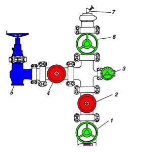
Figure 5
When looking at figure 5 all the valves are orientated with the stem in a horizontal position where valve no 1, 2 and 6 are in a vertical flow and valve 3 and 4 are in a horizontal flow. This is important when it comes to lubricant fittings as the top and bottom points are different. When the valve manufacturer produces the valves they must install the fitting in a way they best can suit the purpose, witch is different installing the valve with the stem vertical or horizontal and installing the valve in a horizontal or vertical flow direction. The top and bottom position will be different I all four cases.
To be continued
Do you want to download this article as a PDF?
Click here to download