Double block & bleed: understanding a barrier – part 3
If looking at a double piston seat arrangement like the one illustrated in Figure 10, you can see that with a system- pressure from the left hand side of the valve the red marked area on the back of the seat will represent the seal-force area of the upstream seat. When decreasing the downstream pressure to zero the cavity pressure will still be 100% of the system pressure, and the seat actual sealing of the valve will, in contrast to the self-relief valve, be the downstream seat. The red marked area on the downstream seat will represent the seal force area, and as long as there is no differential pressure across the upstream seat you don ́t have a clue whether it seals or not.
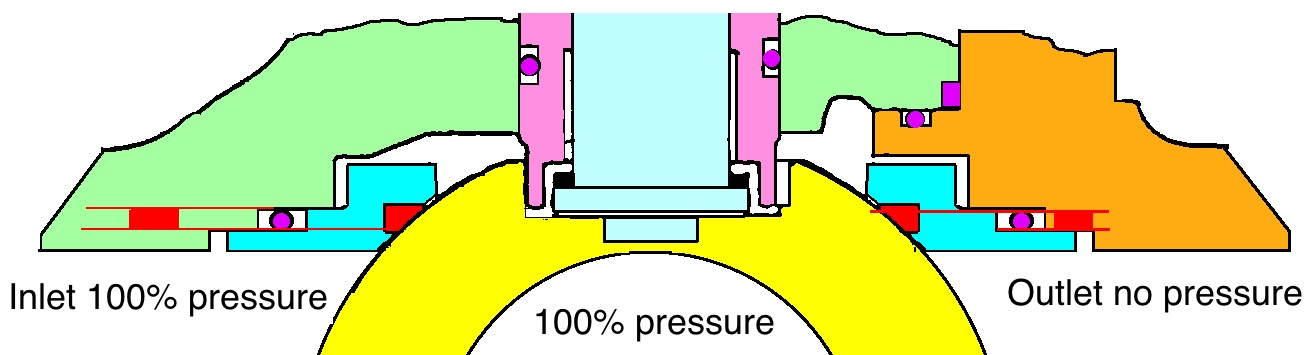
Figure 10
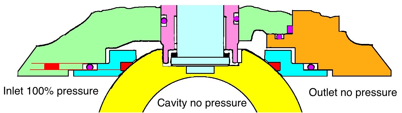
Figure 11
When preparing for a double isolation with this double piston valve the majority of personnel will reduce the cavity-pressure to zero. Looking at Figure 11 you will see what happens. When taking away the cavity-pressure the seal force of the downstream seat will disappear and you are left with a single seal on the upstream seat. You can argue that if you had a seal on the downstream seat it will seal off if the upstream seat starts to leak. But this is not always true. If the force of the coil springs in the downstream seat is not strong enough to overcome the friction between the seat and the seat-pocket, the seat will not follow the ball’s retraction when the cavity-pressure is reduced, and you will have a leaky valve.
To achieve a double isolation on this valve you cannot take away the cavity-pressure as illustrated in Figure 11. You need some pressure in the cavity to keep an active seal-force on the downstream seat.

Figure 12
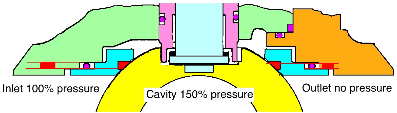
Figure 13
Figure 12 illustrates 50% pressure in the cavity, but you can go down to 10%. Just remember that when lowering the cavity pressure you will reduce the seal force on the downstream seat.
In the event of a low-pressure situation Figure 13 illustrates one other solution
for how to increase the seal force on
both seats of the valve. If you increase
the cavity-pressure (do not exceed the classification) you will increase the seal force of both the downstream and the upstream seats. You can increase the cavity-pressure by using water – N2 – glycol – diesel or any medium acceptable for your purposes.
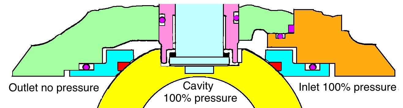
Figure 14
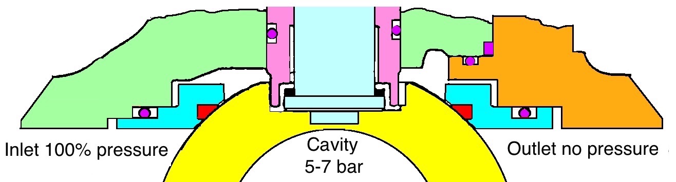
Figure 15
There is one more much used option, and that is the combination of the double piston and self-relief in one valve, the DPE / SPE option. Now there is a seal direction
to consider, as the valve is equipped with two different seat constructions. If there is an arrow on the valve body this does not indicate the flow direction of the valve as the valve is bi directional, but the arrow indicates the seal direction with the DPE seat as a downstream seat.
In Figure 14 the inlet pressure will be from the right hand side and the SPE seat will be upstream and the DPE seat will act as the downstream seat. When the valve is closed and the downstream side is depressurized the cavity-pressure will be 100% system- pressure; there will be a downstream seal on the valve. You can now decrease or increase the cavity-pressure to establish a double seal on the valve as explained in Figures 12 and 13.
What happens if the valve is used with the differential pressure the other way as illustrated in Figure 15? The answer is; the valve is now transformed into a self-relief valve. Looking at Figure 15 the pressure is coming from the left hand side, the downstream side is depressurized and the cavity-pressure will automatically be reduced to balance the coil spring force around 5 – 7 bars.
Figures 10 to 15 are all illustrated with an O-ring as the radial seal on the seat and, as we all know, O-rings are bi directional. O-rings do have a problem called explosive decompression (ED), also called rapid gas decompression. Due to this problem lip seals are more commonly used as the radial seal on the seats. Figure 16 illustrates a double piston construction on the seat, but the seat is actually working as a self-relief seat as the pressure escapes between the seat and the seat pocket whilst the seat seal surface is in contact with the ball at all times.
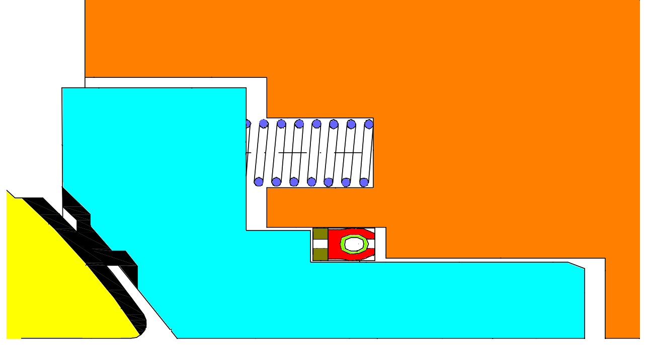
Figure 16
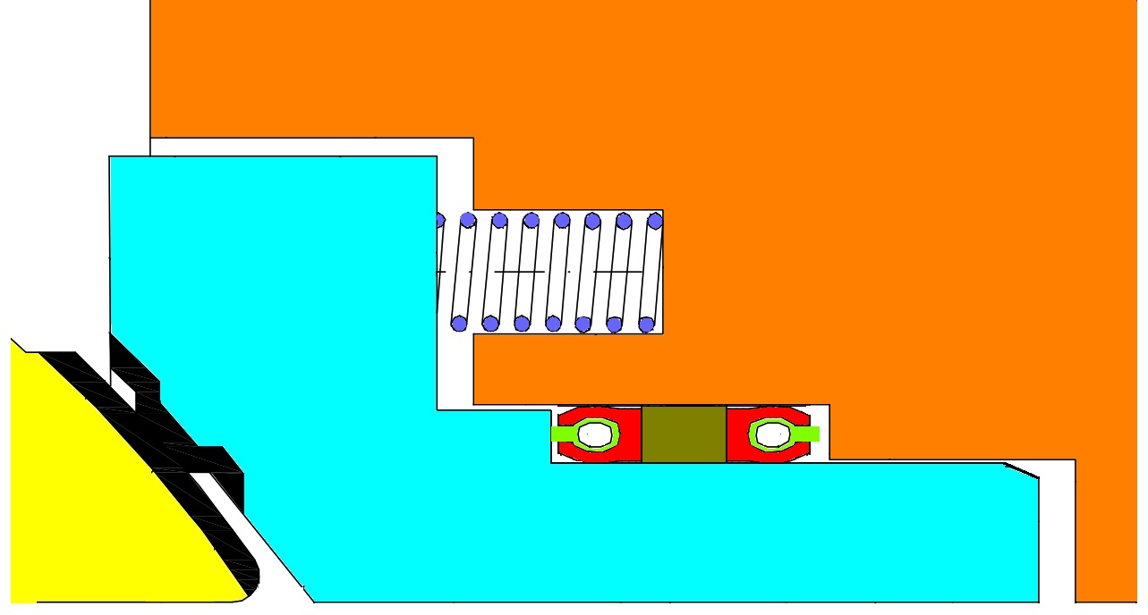
Figure 17
When using a lip seal as the radial seal on the seats used in a DPE / SPE ball valve construction you will normally find one seat with one seal and one seat with two seals as illustrated in Figures 16 and 17. The Figure 17 seat will act as the downstream seat and the Figure 16 as the upstream seat.
To be continued…
Do you want to download this article as a PDF?
Click here to download